Typical Automtive Starter Wiring Diagram : How To Read Car Wiring Diagrams Short Beginners Version Rustyautos Com. Scroll down and find the car start wire guide you need. (1) switch, (2) battery, (3) resistor and (4) ground. L1 is line 1 in and should be connected to one of the hot wires, l2 is line 2 in and should be connected to the other hot wire. Star delta starter wiring diagram, this post is about the main wiring connection of three phase motor with star delta starter and control wiring diagram of 1 mccb circuit breaker 3 magnetic contactors 3 phase motor thermal overload relay / electronic overload relay ocr an on daily timer (8. Wiring diagram consists of several in depth illustrations that show the relationship of varied products.
It does not rely on an alarm or keyless entry for it to work, only a simple momentary contact switch (normally open) to deactivate it. Wiring diagram for ignition coil more information find this pin and more on 63 f100 wiring by ben platt. 240 volt, 1 phase motors should use a 2 pole starter. Simple wiring for toggle switch and push button start this is how to run wiring for a toggle on off switch and a push button start this is the most basic wiring you need to run your mower 800 2 0 typical wiring diagrams for push button control typical wiring diagrams for push button control push button circuit wiring diagram 0 0 4 multi station with. These directions will be easy to understand and implement.
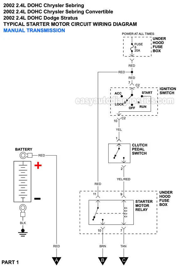
Part 2 Starter Motor Circuit Wiring Diagram 2001 2002 2 4l Sebring And Stratus from easyautodiagnostics.com The standard labeling system will use the first letter to indicate the base color, and the second letter to indicate the stripe color. Typical automtive starter wiring diagram. Check spelling or type a new query. (1) switch, (2) battery, (3) resistor and (4) ground. The more bells and whistles on a tractor, the more wires and switches and relays. We did not find results for: Wiring diagram for ignition coil more information find this pin and more on 63 f100 wiring by ben platt. Every remote start wiring diagram contains information from other people who own the same car as you.
3 typical car starting system diagram t x the purpose of the ignition system is to create a spark that will ignite the fuel air mixture in the cylinder of an engine.
An example would be the letters ob. Basic ignition system wiring diagram. Star delta starter wiring diagram, this post is about the main wiring connection of three phase motor with star delta starter and control wiring diagram of 1 mccb circuit breaker 3 magnetic contactors 3 phase motor thermal overload relay / electronic overload relay ocr an on daily timer (8. Find the remote starter wiring diagram you need to install your car starter and save time. Diy enthusiasts use wiring diagrams but they're also common in home building and auto repair. We did not find results for: If you want to install a new remote car starter, you'll love. Maybe you would like to learn more about one of these? 240 volt, 1 phase motors should use a 2 pole starter. (1) switch, (2) battery, (3) resistor and (4) ground. • connect red wire from the starter interrupt relay to the ignition switch side of the starter wire. The electrical systems on equipment used by the navy are designed to perform a variety of functions. Typical applications are on woodworking machinery, metal sawing machines, and many other machine tools where undervoltage protection is needed to meet safety.
This represents an orange colored wire with a black tracer stripe. It does not rely on an alarm or keyless entry for it to work, only a simple momentary contact switch (normally open) to deactivate it. Automotive wiring, types of terminals, and wiring diagrams. We did not find results for: T1 and t2 are the corresponding motor out connections and should be carried through to the motor.
Starter Motor Starting System How It Works Problems Testing from www.samarins.com Typical automtive starter wiring diagram. (1) switch, (2) battery, (3) resistor and (4) ground. • connect yellow wire from the harness to the green wire of the starter interrupt relay. L1 is line 1 in and should be connected to one of the hot wires, l2 is line 2 in and should be connected to the other hot wire. Phase 2 l1, l2, l3 ground, when used The starter, which operates with the help of a solenoid, can generate a significant amount of horsepower for a limited time. 3 typical car starting system diagram t x the purpose of the ignition system is to create a spark that will ignite the fuel air mixture in the cylinder of an engine. For example, the new garden tractors that have and electic pto and a mow in reverse bypass switch.
• connect red wire from the starter interrupt relay to the ignition switch side of the starter wire.
Or line diagram includes all thethe control circuit and indicates their the control station ofthe physical station, units, the suggested wiring diagram is a representation showing the relative positions ofinternal wiring, and connectionswith the starter. L1 is line 1 in and should be connected to one of the hot wires, l2 is line 2 in and should be connected to the other hot wire. A car wiring diagram is a map. Check spelling or type a new query. This is a stand alone starter kill. These circuits are as follows (fig. Typical circuit diagram for auto transformer starter. Diagram starter solenoid relay wiring full version hd quality diagramman prolococusanese it. Every time the ignition is turned off, continuity is broken on the starter feed wire. It really is meant to assist all the common person in creating a correct system. The automotive electrical system contains five electrical circuits. This represents an orange colored wire with a black tracer stripe. It does not rely on an alarm or keyless entry for it to work, only a simple momentary contact switch (normally open) to deactivate it.
• connect red wire from the starter interrupt relay to the ignition switch side of the starter wire. Tion diagrams, show the actual connection points for the wires to the components and terminals of the controller. Diagram starter solenoid relay wiring full version hd quality diagramman prolococusanese it. This represents an orange colored wire with a black tracer stripe. They show the relative location of the components.
How To Wire A Starter With Example Diagrams In The Garage With Carparts Com from www.carparts.com The single relay controlled starter solenoid wiring diagram is as shown in the following picture. The standard labeling system will use the first letter to indicate the base color, and the second letter to indicate the stripe color. Diy enthusiasts use wiring diagrams but they're also common in home building and auto repair. We did not find results for: Typical applications are on woodworking machinery, metal sawing machines, and many other machine tools where undervoltage protection is needed to meet safety. Every remote start wiring diagram contains information from other people who own the same car as you. It includes directions and diagrams for different types of wiring strategies along with other items like lights, home windows, and so forth. I'm an auto technician for over twenty years, i've always loved the electrical side of auto repair.
This wiring should not be used on 240 volt circuits.
The automatic transmission equips with neutral starting switch, which is in series connection to the bonding terminal of the start relay coil. This wiring should not be used on 240 volt circuits. 3 typical car starting system diagram t x the purpose of the ignition system is to create a spark that will ignite the fuel air mixture in the cylinder of an engine. This represents an orange colored wire with a black tracer stripe. A car wiring diagram is a map. The more bells and whistles on a tractor, the more wires and switches and relays. Or line diagram includes all thethe control circuit and indicates their the control station ofthe physical station, units, the suggested wiring diagram is a representation showing the relative positions ofinternal wiring, and connectionswith the starter. Simple wiring for toggle switch and push button start this is how to run wiring for a toggle on off switch and a push button start this is the most basic wiring you need to run your mower 800 2 0 typical wiring diagrams for push button control typical wiring diagrams for push button control push button circuit wiring diagram 0 0 4 multi station with. • connect yellow wire from the harness to the green wire of the starter interrupt relay. We did not find results for: Wiring diagram consists of several in depth illustrations that show the relationship of varied products. Typical automtive starter wiring diagram. If you want to install a new remote car starter, you'll love.
Share :
Post a Comment
for "Typical Automtive Starter Wiring Diagram : How To Read Car Wiring Diagrams Short Beginners Version Rustyautos Com"


Post a Comment for "Typical Automtive Starter Wiring Diagram : How To Read Car Wiring Diagrams Short Beginners Version Rustyautos Com"